
What is a diaphragm compressor?
Diaphragm compressors move (and compress) gas using a set of three, flexible diaphragm membranes. Gas enters the compressor’s process head from an external tank or process on its down-stroke. On the up-stroke, the diaphragms flex, reducing the area inside the chamber, pushing the gas out of the compressor (and on to the process/application).
The oscillating movement of the diaphragms is driven by a reciprocating piston and crankshaft mechanism. Only the process diaphragm and the compressor’s process head come in contact with the gas. This is important because the diaphragms prevent hydraulic fluid (or oil from the compressor) from coming in contact with the process gas. This eliminates any potential contamination of the gas, which is critical with Hydrogen applications, because the purity of the gas has a direct impact on the process. For these reasons, diaphragm compressors are also preferred for pumping toxic or explosive gases. The diaphragm must be reliable enough to resist fatigue while also having adequate chemical properties for corrosion resistance.
Sundyne’s PPI Diaphragm Compressors combine two systems – a hydraulic system and a gas compression system. A series of metal diaphragms isolate components between the two systems.
- The gas compression system consists of three (3) flat metal diaphragms, which are clamped between two precisely contoured and concaved cavities, and the process gas inlet and outlet check valves.
- The hydraulic system includes a motor-driven crankshaft, which reciprocates a piston in the hydraulic fluid medium. This positive displacement piston causes the hydraulic fluid to be compressed against the lower side of the diaphragm group which, in turn, causes the diaphragm group to sweep the cavity, displacing the process gas.
The other components in the hydraulic system include:
- Hydraulic check valve – prevents back driving of the hydraulic fluid during the up stroke.
- Hydraulic over-pump valve – assures that the diaphragm fully displaces the process gas in the cavity on each stroke.
- A cam-driven Injection pump – provides make-up hydraulic fluid to ensure that the hydraulic system is always full of hydraulic fluid for the compressor stroke. It also facilitates fast priming after extended compressor shutdown and maintenance.
Compressors with Injection Pumps:
The cycle of operation for a diaphragm compressor begins with the diaphragm group fully deflected to the bottom of the cavity by the process suction pressure. The hydraulic piston is at Bottom-Dead-Center (BDC) and the hydraulic system has just received the output of hydraulic fluid from a single stroke from the injection pump.
On the process side of the diaphragm, the cavity is now filled at a given suction pressure level with the process gas, which has entered through the inlet check valve. As the crankshaft rotates and the hydraulic piston moves from its BDC position toward Top-Dead-Center (TDC), the hydraulic pressure inside of the head increases. This occurs because the hydraulic system’s injection and return lines are blocked by the hydraulic check valve and hydraulic over-pump valve. As the piston continues toward TDC, and the hydraulic pressure reaches the pressure level of the process gas in the cavity, the diaphragm sweeps the cavity towards its TDC position, compressing the process gas. When the pressure of the process gas in the cavity reaches the pressure level downstream of the discharge check valve, the check valve opens, and the process gas is discharged from the cavity.
With the diaphragm in a fully deflected discharge position, the piston still has a certain amount of travel required to reach its TDC position. As the piston moves to TDC, the additional hydraulic oil volume is compressed through the hydraulic over-pump valve, which is set at a pressure level above the desired process gas discharge pressure, ensuring full volumetric efficiency of the head. At this point, the compression portion of the cycle has been completed.
The hydraulic piston now moves toward BDC. As it does, the diaphragm is deflected toward the bottom of the cavity by both the expansion of the residual gas contained in the clearance volume and by the additional suction gas pressure entering the cavity through the check valve. During the suction stroke, a synchronized auxiliary eccentric cam on the crankshaft causes the hydraulic injection pump plunger to stroke. This injects an amount of hydraulic fluid that is approximately equal to that which was lost through the hydraulic over-pump valve at the end of the compression portion of the cycle. When the hydraulic piston reaches its BDC position, the hydraulic system is again full of hydraulic fluid. Since the diaphragm group is now in the BDC position, a full gas cavity is assured. The cycle is now completed.
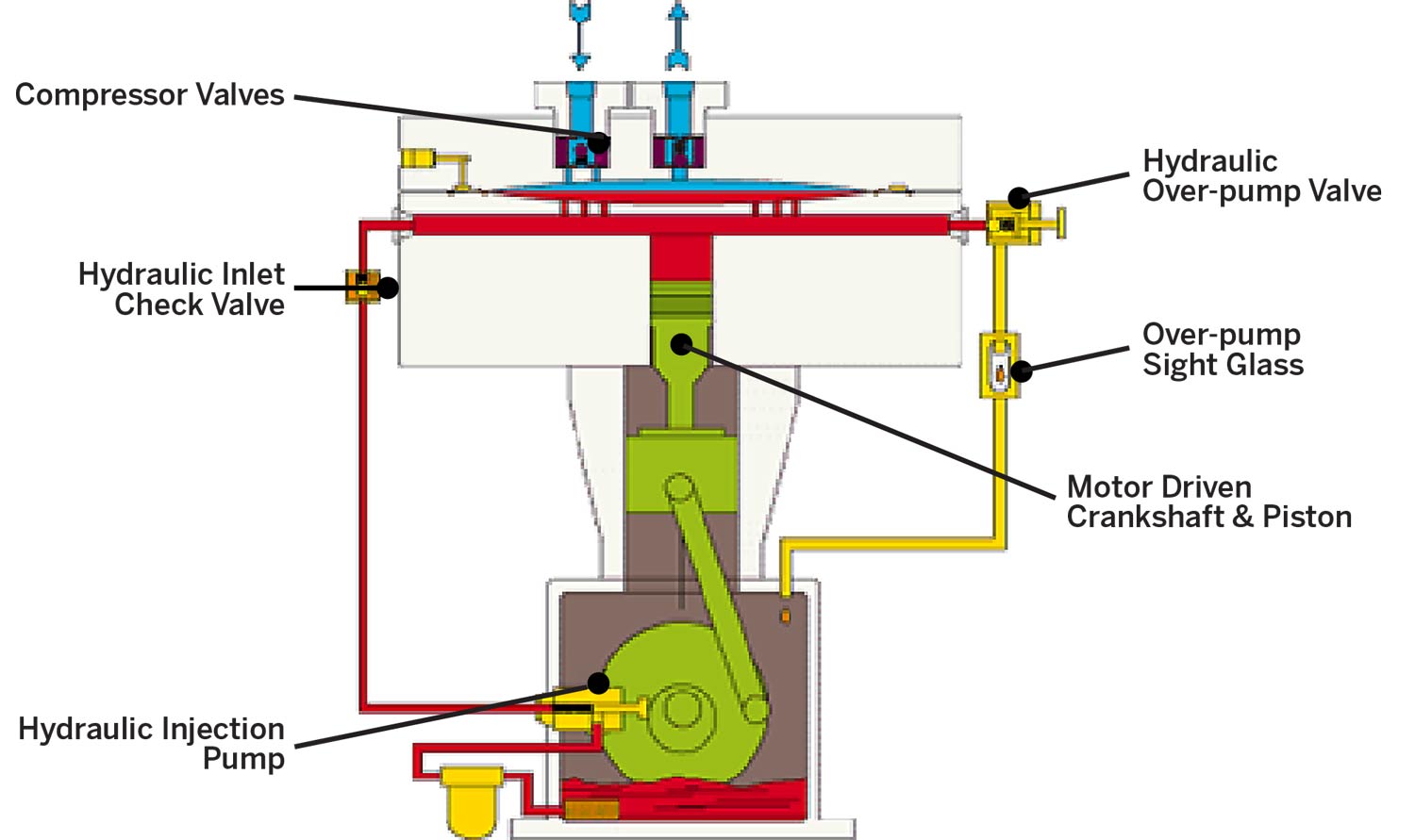
Typical System Components
- Compressor Valves
- Hydraulic Inlet Check Valve
- Motor Driven Crankshaft & Piston
- Hydraulic Over-pump Valve
- Over-pump Sight Glass
- Hydraulic Injection Pump
To learn more about Sundyne’s line of PPI Diaphragm compressors, please click here.


